As part of our ongoing efforts to improve tooling for hardware verification and software–hardware co-design, we extended Verilator with support for native fault-injection mechanisms.
Verilator in its current upstream version does not provide built-in fault-injection capabilities, which are essential for investigating hardware behavior under unexpected error conditions.
Existing solutions either require manual HDL modifications or rely on external tools that reduce performance and need continuous maintenance to ensure compatibility with current simulator versions.
There are some ideas for adding native fault-injection support to Verilator by adding custom fault objects or assignment operator overloading.
The AEMY team aims to integrate a native fault-injection mechanism directly into Verilator to preserve its speed and ensure long-term support.
In contrast to the existing ideas, we follow the concept of hooking into interesting parts of the design in order to inject faults.
As a first step towards this, we are extending verilator to add DPI-hooks, which we reference as hook-insertion.
This term does not reference the actual fault injection, but instead references adding DPI-hooks to provide an interface external code can use to observe or modify signals.
The fault-injection can then be done through these DPI-hooks during the simulation.
By aligning the feature with Verilator’s existing configuration options, users will be able to run fault campaigns efficiently and without additional tooling.
The targeted upstream integration ensures ease of use, high performance, and long-term reliability.
For further background and motivation, see “Fault-injection support with the Verilator simulation tool” in the Isolde project overview.
Below is a concise overview of how to use the feature and the changes introduced to support it.
Use-case example
Since it is always easier to understand such a feature with an example, we provide a small example below to illustrate how the added feature can be used. Let’s begin with a simple counter module:
module counter (
    input logic clk,
    input logic reset,
    input logic en,
    output logic [31:0] counter_out
);

    logic [31:0] counter_reg;

    always_ff @(posedge clk or posedge reset) begin
        if (reset)
            counter_reg <= 32'd0;
        else if (en)
            counter_reg <= counter_reg + 32'd1;
    end

    assign counter_out = counter_reg;

endmodule
Next, we define a top module that instantiates several controllers, each of which instantiates the counter module. This lets the example demonstrate instance hierarchies, while keeping the complexity as low as possible:
module top (
    input wire clk,
    input wire reset,
    output wire [31:0] counter1,
    output wire [31:0] counter2,
    output wire [31:0] counter3,
    output wire [31:0] counter4,
    output wire [31:0] counter5
);

    controller uut(clk, reset, counter1);
    controller uut1(clk, reset, counter2);
    controller uut2(clk, reset, counter3);
    controller uut3(clk, reset, counter4);
    controller uut4(clk, reset, counter5);

endmodule

module controller(
    input wire clk,
    input wire enable,
    input wire reset,
    output wire [31:0] counter
);

    counter cut(clk, reset, counter);

endmodule
With the design in place, the next step is to decide which signals to target for hook insertion. The feature supports inserting hooks on multiple signals by adding multiple configuration lines.
Since we’ve reached the configuration step, let’s show how to configure hook insertion for a specific signal.
The feature extends Verilator’s configuration format file (typically .vlt) with entries that describe hook insertion. Each entry specifies:
- the target signal path
- the C/C++ callback function name
- an ID used to select different fault behaviors inside the callback
An expected configuration line for the hook-insertion looks like:
insert_hook -callback "<c-function name>" -id <fault-id> -target "<topmodule.instance.instance.instance.var>"
Let’s go through this configuration line and elaborate what each flag needs as input, using our example.
Starting with the insert_hook flag, this flag represents the keyword to enable the hook-insertion and therefore does not need an input.
Continuing with the -target flag, which is probably the more complicated flag in this configuration. It defines the amount and which signal we want to hook-insert as stated earlier. For this example we want to hook-insert one signal, which will be the counter_reg signal. Since the -target flag needs the path to the variable as input, this “target”-path should start with the top module followed by the instances calling the module containing the targeted signal.
It does not matter if the instance calls the module directly or indirectly; as soon as it is in the path it must be part of the target string. Let’s look for the signal’s position in the model.
The signal can be found in the counter module, which in turn is called by the controller module via the cut instance. Additionally it is indirectly called from the top module via a variety of instances. Since we have different instances in the top we also need to define which specific instance, containing the target signal, should be targeted. In this scenario this will be the instance uut1.
To now form the correct -target string from this signal path, we need to omit all intermediate module names except the top module and apply the format shown above.
This will result in the following string for the target flag, which needs to be added to the configuration line:
top.uut1.cut.counter_reg
For the next flag we cover the -callback flag.
This flag takes the name of the callback function defined on the C side of the DPI as input. In our example we will name the callback function faultInjection(), leading to this name as input for the flag.
Lastly, let’s cover the -id flag.
This flag provides advantages especially if multiple signals are hook-inserted using the same callback function. The flag can be used to select a specific case or scenario if different scenarios are defined in the callback function. This selection can be implemented via a switch case statement.
If the callback needs no variants, set -id to 0 or any fixed value. In this example we use id 0 for stuck-at-0 and 1 for stuck-at-1. (We chose 1 for a stuck-at-1 case for the counter_reg)
All these steps should result in the following configuration file, which we named verilator.vlt for this example:
`verilator_config

insert_hook -callback "faultInjection" -id 1 -target "top.uut1.cut.counter_reg"
With the Verilog/SystemVerilog sources and the .vlt configuration ready, we now provide the C/C++ side of the DPI interface. In this example we want to provide fault-injection, therefore we define a fault model for the signal in our .cpp file (here fault_models.cpp). This file will contain our callback function called faultInjection().
An illustrative callback implementation might look like this:
#include <svdpi.h>
#include <verilated.h>

extern "C" int faultInjection(int id, svBit trigger, const int verilogInput) {
    static int out;
    switch(id) {
    case 0:
        if(VL_TIME_Q() >= 50 & VL_TIME_Q() <= 70) {
            return 0;
        } else {
            return verilogInput;
        }

    case 1:
        if(VL_TIME_Q() >= 10 & VL_TIME_Q() <= 50) {
            return 1;
        } else {
            return verilogInput;
        }
    default:
        return verilogInput;
    }
}
The verilated.h header provides access to simulation time via VL_TIME_Q(), which is useful for time‑dependent faults.
Now we can run Verilator with the --timing and --insert-hook flags to enable the hook-insertion and hook trigger. Example build and run commands could look like this:
verilator --exe --build --trace -cc --timing --insert-hook \
  --top-module top \
  top.v counter.v \
  verilator.vlt \
  sim_main.cpp fault_models.cpp

./obj_dir/Vtop
We also include --trace to enable waveform tracing.
Executing the above build and run commands will produce the following waveform output:
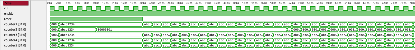
All counters count on the rising clock edge and remain at their initial value while reset is active. The only counter behaving differently is counter2 (the instance uut1 in this example), which we targeted with hook insertion. As expected, the fault affects the counter output during the configured time window (10–50) with the value 1.
This example demonstrates the feature’s capabilities. Next, we briefly explain how the extension works and note current limitations.
How the extension works
The extension inserts DPI call hooks into the generated model automatically. Without automation, manually adding DPI calls and the surrounding logic becomes tedious when many signals are involved. Our extension modifies Verilator to insert the required statements for us.
We implement this by transforming Verilator’s Abstract Syntax Tree (AST) during compilation to C++. Transformations include duplicating modules when needed (so the tool can select between original and hook‑inserted versions), adding variables and helper functions, creating additional assignments, and inserting a hook trigger that forces the DPI call even when the original model output has not changed. Because the trigger relies on timing behavior, the --timing flag must be used when running Verilator.
The hook insertion can be enabled by the user with the --insert-hook flag when building.
After the AST transformations, Verilator generates hook‑inserted C++ code. The user provides a .cpp file implementing the fault model, which Verilator compiles into the simulator.
Why use the DPI?
The Direct Programming Interface (DPI) is a SystemVerilog feature that allows SystemVerilog to call functions implemented in another language (typically C or C++). It keeps the implementation modular and enables integration with other languages (for example, Python via bindings).
There are three main reasons for us to prefer DPI hooks over hard‑coding faults into Verilator itself:
- DPI provides a way to keep the Verilator optimizations and therefore keep the fast simulation times.
- DPI calls occur late in the evaluation order of simulation, reducing the risk of masked or overwritten values.
- DPI is general purpose and reusable beyond fault injection, keeping the implementation modular.
Although DPI is defined for SystemVerilog, Verilator treats Verilog sources as SystemVerilog for DPI purposes, so the mechanism also works for Verilog models.
Current limitations
The extension is functional but currently has a few limitations:
- You cannot yet insert hooks directly into the top module of a design.
- Targeted signals must be either implicit or literal types.
- Targeted signals must be no wider than 64 bits.
We plan to address these limitations in future work. Despite them, the approach provides a flexible fault injection capability without adding Verilator features tied to one specific use case.
A draft pull request for adding this extension to Verilator can be found here.
Outlook
With this foundation, our focus will shift more towards a framework that will use this feature to enable large-scale fault injection campaigns and analysis of the effects of the injected faults. This framework will hopefully assist hardware developers in creating more stable and secure hardware systems.